FAQ H0 Scale
Locos / Railcars
23.09.2025 Steam Distillate Not to Be Used for PIKO Smoke Generators
The steam distillate from ESU is not suitable for PIKO smoke generators.
Using it may cause irreparable damage to the PIKO smoke generator in use.
02.04.2025 Diesel Locomotive DE18 - Documentation and CV Table for the Light Controller
The vehicle contains an additional controller for the lighting functions on the vehicle’s circuit board.
This controller operates like a SUSI function decoder and can be configured via CV programming.
The documentation and CV table in PDF format provide information on the required programming. The numbering of the outputs should be considered independently of the numbering of the locomotive decoder.
Download PDF Documentation LCDownload PDF LC CV Table
If necessary, please activate the output of SUSI data on your decoder. Some decoders are set by default to output simple logic levels instead of SUSI data. Please refer to the manual of the decoder manufacturer. PIKO XP decoders activate SUSI data output if bit0 is written to 1 in CV47.
12.02.2025 GTW ‘Stadler’ / BR 440 interior lighting in digital mode
Problem:
After digitisation with an 8-pin NEM652 decoder, the interior lighting is switched on with the function key F0 and not with F1.
Cause:
The wiring on the vehicle board is designed ex works so that the interior lighting is switched on in analogue mode with a jumper plug parallel to the front lighting.
Solution:
Solder the green cable from the light output (X) to the solder pad for the decoder output A1 (Y) as shown in the following document.
See PDF
29.11.2024 BR 003 Expert Plus - Special function mapping of the additional controllers for the lighting functions
The vehicle has an additional controller for the light functions on the vehicle circuit board.
This controller works like a SUSI function decoder and can be set via CV programming.
The CV table in the PDF provides information on the programming to be used. The numbering of the outputs is independent of the numbering of the locomotive decoder.
Download PDF
02.07.2024 Vectron Dual Mode - Special function mapping of the additional controllers for the lighting functions
The vehicle has an additional controller for the light functions on the vehicle circuit board.
This controller works like a SUSI function decoder and can be set via CV programming.
The CV table in the PDF provides information on the programming to be used. The numbering of the outputs is independent of the numbering of the locomotive decoder.
Download PDF
If necessary, please activate the output of SUSI data on your decoder. Some decoders are set by default to output simple logic levels instead of SUSI data. Please refer to the manual of the decoder manufacturer. PIKO XP decoders activate SUSI data output when bit0 is written to 1 in CV47.
02.07.2024 Diesellok SP 9000 / ML 4000 - Special function mapping of the additional controllers for the lighting functions
The vehicle has an additional controller for the light functions on the vehicle circuit board.
This controller works like a SUSI function decoder and can be set via CV programming.
The CV table in the PDF provides information on the programming to be used. The numbering of the outputs is independent of the numbering of the locomotive decoder.
Download PDF
If necessary, please activate the output of SUSI data on your decoder. Some decoders are set by default to output simple logic levels instead of SUSI data. Please refer to the manual of the decoder manufacturer. PIKO XP decoders activate SUSI data output when bit0 is written to 1 in CV47.
15.01.2024 Steam locomotive BR 03 - Occurring noise with switching on the light function F0
As soon as the light function F0 is switched on, an additional sound can be heard.
Cause:
This sound is the sound of the "generator", which in the original generates the current for the lighting.
Solution:
If this is not desired,
1) the complete vehicle sound can be switched off via the function key F14 (tunnel mode), or
2) the volume of the generator can be set to 0 by programming the decoder as follows:
CV31 = 16
CV32 = 0
CV292 = 0 (factory setting 100)
Alternatively, if a PIKO SmartProgrammer is available, the extended function mapping can be changed in such a way that the link between the light function F0 and the generator sound is cancelled.
29.11.2023 EN57 electric multiple unit - Special function mapping of the additional controllers for the lighting functions
These controllers can be set as required via CV programming.
The CV table in the PDF provides information about the options, the factory settings and the programming to be used.
The function outputs of the installed locomotive decoder are not used!
Download PDF
If necessary, please activate the output of SUSI data on your decoder. Some decoders are set by default to output simple logic levels instead of SUSI data. Please refer to the manual of the decoder manufacturer. PIKO XP decoders activate SUSI data output when bit0 is written to 1 in CV47.
28.11.2023 Giruno electric multiple unit - Special function mapping of the additional controllers for the lighting functions
These controllers can be set as required via CV programming.
The CV table in the PDF provides information about the options, the factory settings and the programming to be used.
The function outputs of the installed locomotive decoder are not used!
Download PDF
If necessary, please activate the output of SUSI data on your decoder. Some decoders are set by default to output simple logic levels instead of SUSI data. Please refer to the manual of the decoder manufacturer. PIKO XP decoders activate SUSI data output when bit0 is written to 1 in CV47.
21.08.2023 Which capacitors can I use as support capacitors in H0 vehicles?
Here you can find further information and a selection of suitable capacitors for download.
21.08.2023 Special feature sound decoder 52936 / 52938 / 52940
On locomotives 52936, 52938 and 52940, by pressing function key 8 (driving sounds) several times, the two motors can first be started one after the other. If the button is pressed a third time, the engine noise switches off again. Pressing it a fourth time deactivates the vehicle sound completely.

13.12.2022 Giruno electric multiple unit suddenly stops after rapid acceleration
Since these are set relatively conservatively ex works for the best possible protection of the decoder, the following CV settings provide a remedy:
CV57 = 160
CV59 = 192
08.07.2020 G6 MTU Sound – The motor sound does not work after switching on function F1
18.12.2019 VT 2.09 / VT98 How do I adjust the behaviour of the lighting for a Märklin® braking distance correctly?
For the lighting of the VT 2.09 / VT98 in a Märklin® brake section to work correctly, the analogue mode in the lighting unit (not the vehicle decoder) must be switched off.
Switching the analogue mode on / off via the interior lighting with a digital control unit (in the original with F3, light output A3).
Procedure:
Switch off F3.
Switch the light on and off 3 times within 5 seconds (press the F3 key 6 times).
The railcar flashes 2x with the interior lighting, if the analogue mode is now switched off.
The railcar flashes 3 times with the interior lighting if the analogue mode is now switched on.
You can switch between the two settings at any time.
If the analogue mode is switched off, the light is controlled in the same way as the built-in decoder. Only the decoder then decides how the light is to be switched in analogue mode and on braking sections.
It may be necessary to make adjustments to the function mapping in the decoder in order to obtain the desired lighting scheme.
When the analogue mode is switched off, no light is switched on in pure analogue mode with a jumper plug.
In order for the light to function again in purely analogue mode, the analogue mode must be reactivated with a decoder in digital mode.
28.08.2019 What has to be considered when removing the case of the ICE 4 (51400 et seqq.)?
To make it easier to remove the case from the chassis, please also pay attention to the detent lugs at the ends of the cars. These can still block a little when the case is first loosened. In the following you can see where they are located and how to proceed.
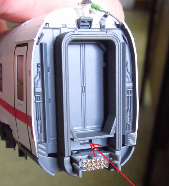
Figure 1) At this point below the bellows there is a small detent lug which must be additionally pressed in after removing the screws. Only then the housing can be easily lifted off the chassis.
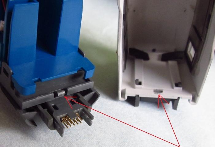
Figure 2) Shows the detent lug and the detent surface.
Overbuffering when using close couplers in our hobby locomotive BR 182 / BR 185 and BR 189
As our hobby Taurus locomotives BR 182, BR 185 and BR 189 have no close coupling , operating with close couplers between locomotives and cars is not possible for technical reasons.
For locomotives in the hobby program, this is not necessary in our view.
However, since there are some PIKO fans who use our hobby locomotives because of their good and consistent runnability on club layouts, they want a short coupling operation.
However, one can create a workaround for this problem with some crafting skills.
How? We like to explain it to you here:
In the same time we would like to point out that through your work on the locomotive a possible warranty claim can be forfeited.
1. Tools
You need the following tools:
- rasp
- calipers
- screwdriver
2. Changes
Remove the coupling shaft as follows:
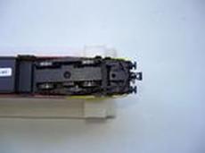
Turn your model on its head, so that you can remove the coupler shaft on the bottom of the model .
Please note that you use a foam pad, so there is no damage to the roof equipment.
picture 1
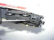
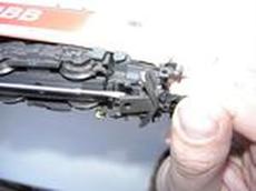
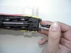
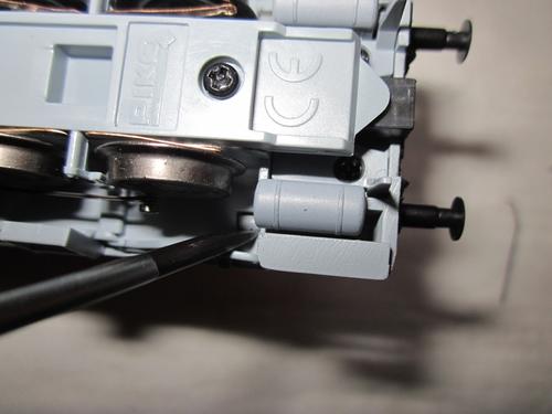
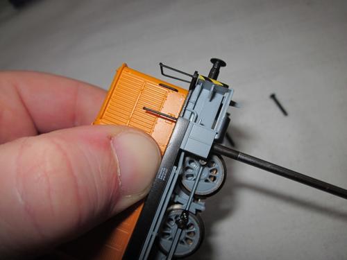
Gently press the cowcatcher up with a screwdriver as far as necessary so that you can pull the shaft out forwards (pictures 2-4). Please pay attention to the fine resetting springs on the shaft, these must not be deformed. The installation of the shaft is carried out in reverse order.
picture 2 picture 3 picture 4
Then rasp out according to the drawing at a distance of 3 mm (measured from the front) a 1.3 mm wide slit in the longitudinal sides of the coupling shaft on both sides so that you can see through:
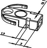
When rasping please leave sharp edges, so that a solid latching occurs, so the couplers cannot be easily pulled out.
3. Additional parts
Get our spacers (item number 56036) which were especially developed by us to extent the close coupler shafts of our models.
Here are 2 pieces in each box.
4. Extension with spacer
Slide the PIKO spacer over your close coupler.
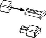
5. Usage in NEM
Insert the short coupling with the spacer in the standard shaft until it clicks into the rasped out slot.

If the close coupling is not properly locked into place, you have to rasp again until a solid latching is possible. Please remember that the latching has to pull your train!
Now your locomotive is ready for operation with close couplers.
Can you mount traction tires on a E93?
1. Tools
You need the following tools:
- Stable padded surface for the model
- A key according to the following drawing
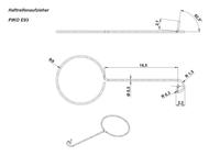
- Tweezers
- Blade screwdriver
2. The workflow is as follows:
Turn your model on its head, so that you can start mounting the traction tires Please note that you use a foam pad, so there is no damage to the roof equipment.
 Now place the traction tires loosely on the wheel, on which you have already removed the traction tire and where you want to mount a new one.
 Now pull the new traction tires loosely over the entire wheel.
 Then insert the key with the protruding pin between the tire and the wheel.
Here, the curved front piece of the key should rest outside on the wheel rim. From above, please press with your fingers or with the tweezers on the traction tire, so it cannot slide down from the slot in the wheel.
 Now run the mounting key around the entire wheel with light pressure against the body of the wheel. During this process hold down the traction tire with thumb or tweezers and press it into the groove.
 Finally switch on the current of your model layout to a pair of wheels and turn the transformer to the extent so that the wheels turn slowly.
Simultaneously press with a blade screwdriver on top of the exchanged traction tire so that it can be put right into the groove.
If this seems to be too complicated for you, ask your local dealer if he will change the traction tires for you.
Are PIKO models suitable for digital operation?
All PIKO locomotives (except BR 38, Kö I and hobby steam locomotive 50500/50501) for the DC system in our range have a digital interface (for the type of interface, see product details). If a digital operation is desired, the decoder only needs to be inserted into the loco's interface. The AC models of our range are already equipped with a digital decoder.
Is there a interior lighting for the PIKO ICE 3?
For our ICE 3 the installation of interior lighting is not provided. Therefore, we also do not offer any conversion kit for retrofitting.
What to consider when opening the V60?
1) Remove the 4 handles on the cab.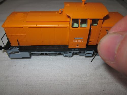
2) Unscrew the screws on the right and left bottom of the cab.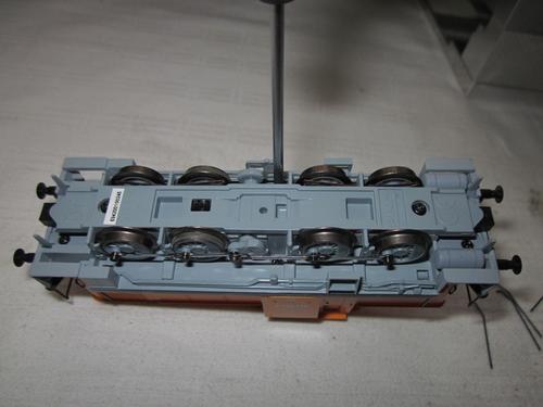
3) Carefully unclip the 4 latches (2 on each side of the frame) with a screwdriver from the frame.
Please be careful so that the latching lugs do not break.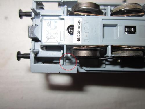
4) Remove the body carefully.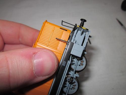
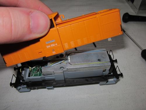
5) Please note that when you remount the body that the latches snap into place by their own.
Turn the screws back in and then mount the handles again on the model.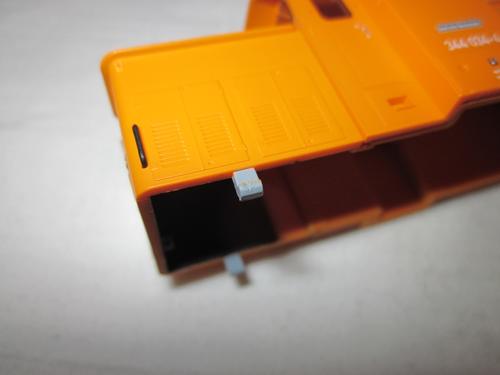
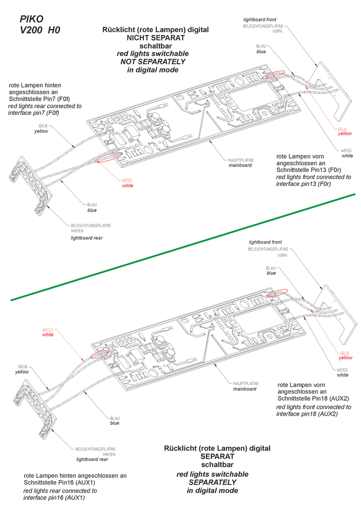
Red light switching of the H0 V 200 / BR 220 in digital mode
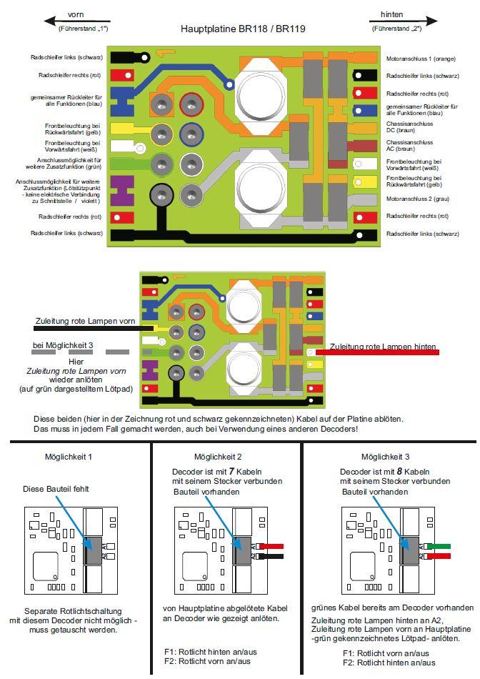
Red light switching of the H0 BR 118 / BR 119 in digital mode
If the tail light (red) should be separately turned on and off, the wiring must altered as shown below:
► PDF download of the scheme to enlarge
Fern-/Rangierlichtschaltung H0 T669 / 770 im Digitalbetrieb

(1) Anschlüsse Lautsprecher
(2) Anschlussmöglichkeit Speicherkondensator
(Elko - max. Baugröße ca. ø10,5 x 21), über die Lötbrücken K1 und K2 kann gewählt werden, ob der Plus-Anschluss des Kondensators an Pin6 (K1 geschlossen), Pin9 (K2 geschlossen) oder beiden (K1 und K2 geschlossen / Pin6 und Pin9 damit direkt verbunden) der PluX-Schnittstelle angeschlossen wird.
Eine von einigen Decoderherstellern geforderte Ladeschaltung dafür (Widerstand zur Ladestrombegrenzung, Freilaufdiode) ist nach Angaben des jeweiligen Herstellers vom Betreiber bei Bedarf selbst in geeigneter Weise zu installieren.
Die seitlichen Kennzeichenbeleuchtungen sind werksseitig parallel zu den Frontlichtern geschaltet.
Durch Umstecken von J1 lassen sich diese digital separat schalten (werksseitig über die geschlossene Lötbrücke K3 mit AUX7 -Pin22- verbunden).
Durch Öffnen von K3 und Schließen von K4 kann diese alternativ an AUX6 (Pin21) geschaltet werden.
Das Entfernen des Jumpers J2 deaktiviert das obere Frontlicht vorn, das des Jumpers J3 das entsprechende hinten.
Über Ausgang AUX3 (Pin2) lässt sich ein Rangierlicht schalten. Dabei leuchten alle 4 unteren weißen Lampen (2x vorn und 2x hinten).
Weitere Informationen können dem beigefügten Schaltbild entnommen werden. (Schaltbild als PDF herunterladen)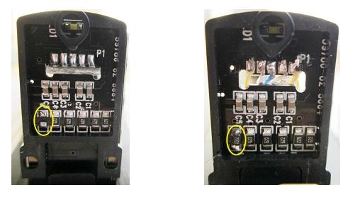
Durch Nachbestückung der Widerstände R6 auf den Licht-Platinen kann ein Fernlicht
(der beiden oberen Scheinwerfer hinten / vorn) realisiert werden.
Im gezeigten Beispiel wurden Widerstände 2K7 verwendet, die „reguläre“ Beleuchtung ist gedimmt.
Schaltbar ist dieses Fernlicht über AUX4 (Pin19 / vorn) bzw. AUX5 (Pin20 / hinten).
Waggons
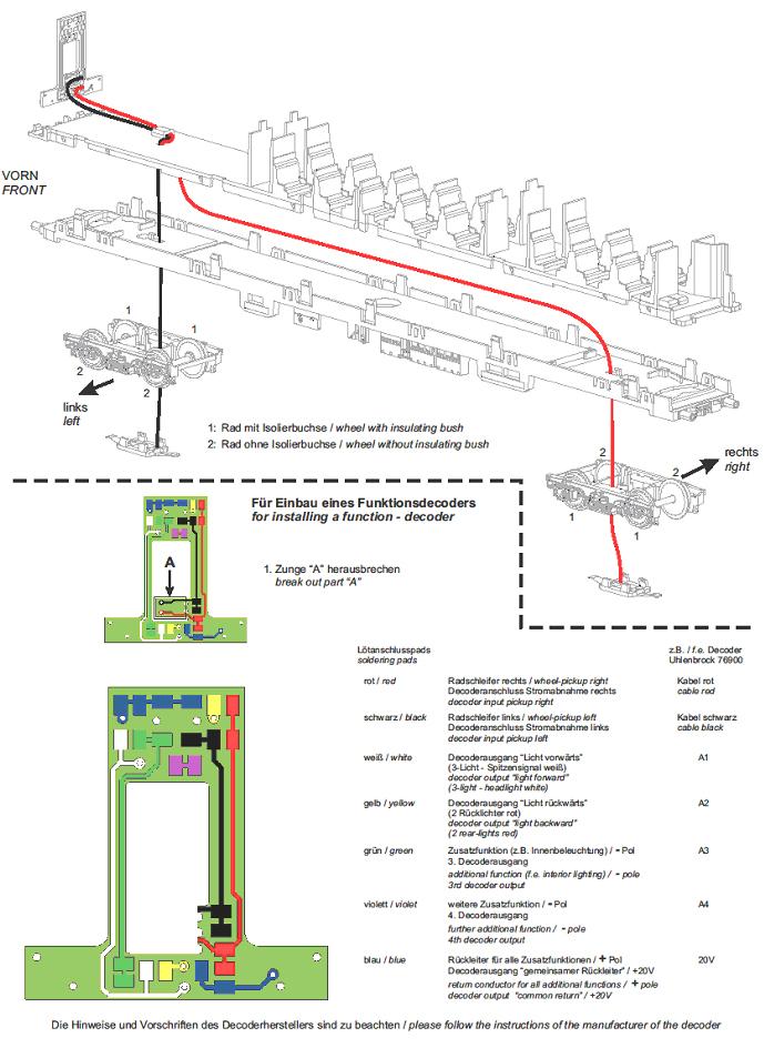
Directional light changing (red/white) in digital mode - 1.) Silberling control car (#57652):
| The white / red light change of the control car must be controlled in digital mode with a function decoder. The decoder is soldered. Below you will find the appropriate connection diagrams. |
 |
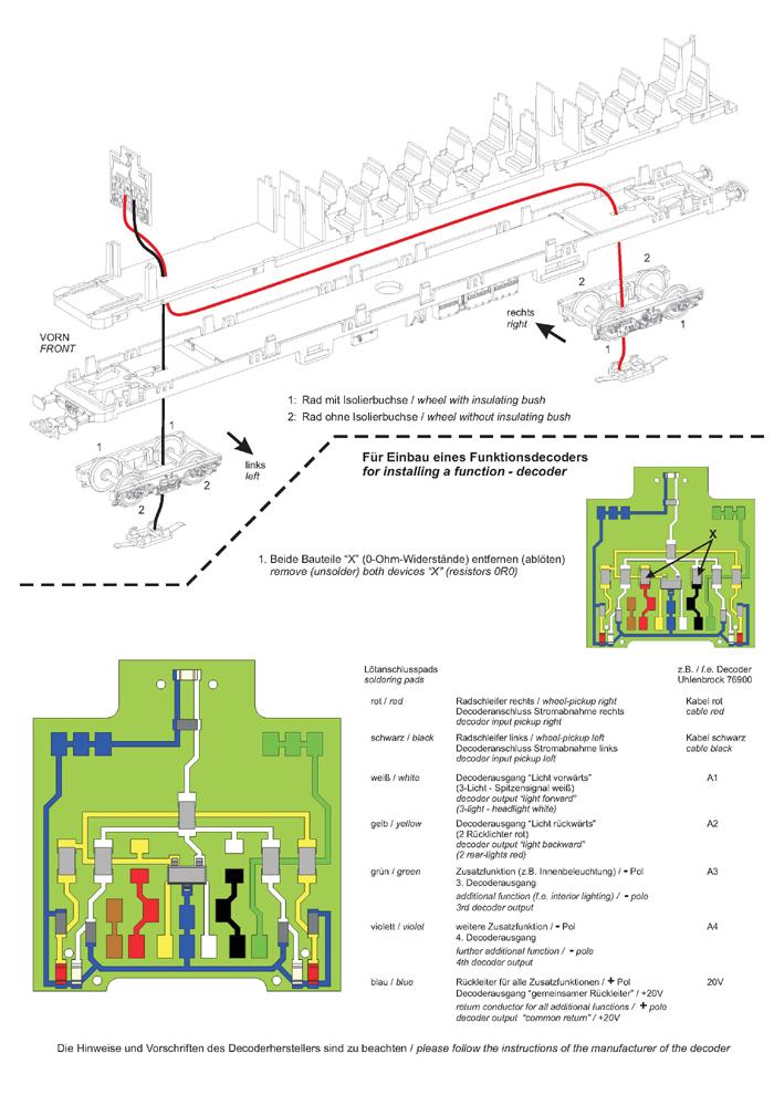
Directional light changing (red/white) in digital mode - 2.) Silberling control car (#57653 / 57656 / 57659):
| The white / red light change of the control car must be controlled in digital mode with a function decoder. The decoder is soldered. Below you will find the appropriate connection diagrams. |
 |
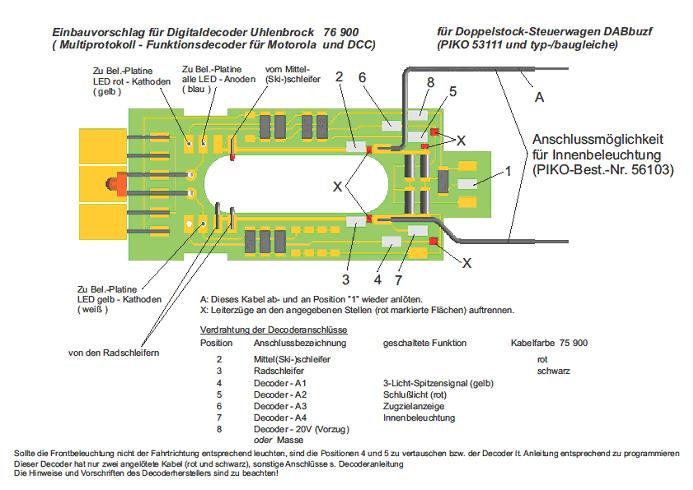
Directional light changing (red/white) in digital mode - 3.) Bi-level control car Classic:
| The white / red light change of the control car must be controlled in digital mode with a function decoder. The decoder is soldered. Below you will find the appropriate connection diagrams. |
 |
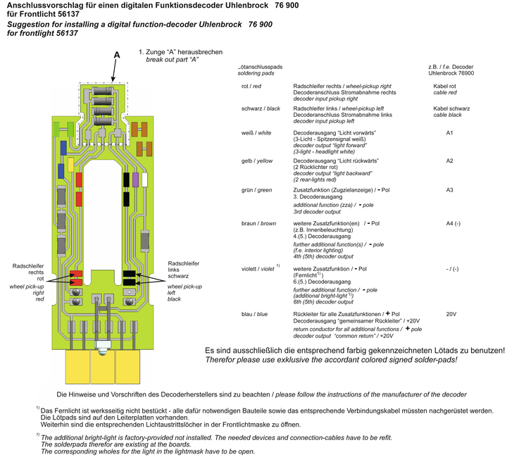
Directional light changing (red/white) in digital mode - 4.) Bi-level control car Hobby (#57603 / 57621):
| The white / red light change of the control car must be controlled in digital mode with a function decoder. The decoder is soldered. Below you will find the appropriate connection diagrams. |
 |
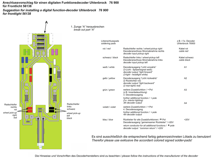
Directional light changing (red/white) in digital mode - 5.) Bi-level control car Hobby (#57623):
| The white / red light change of the control car must be controlled in digital mode with a function decoder. The decoder is soldered. Below you will find the appropriate connection diagrams. |
 |

